2 Stress
Having reviewed static equilibrium in Chapter 1, we know how to find the internal loads in a body using equilibrium. When determining whether a body can resist the loads applied to it, keep in mind that the internal load is only part of the solution. The dimensions of the body and the inherent properties of the material it is made from are also important.
In this chapter we explore the concept of stress, which can help us determine whether an object will physically break when subjected to a load. We cover average normal stress (stress perpendicular to the cross-section) in Section 2.1 and average shear stress (stress parallel to the cross-section) in Section 2.2. We then discuss bearing stress (the stress between two bodies in contact with each other) in Section 2.3 and finish with the average normal and shear stresses on an inclined cross-section in Section 2.4.
2.1 Average Normal Stress
Click to expand
Average normal stress is defined as the internal normal force divided by the cross-sectional area of the body. By convention, it is represented by the Greek letter sigma (σ). Stress increases as the force increases or as the cross-sectional area decreases.
\[ \boxed {\sigma=\frac{N}{A}}\text{ ,} \tag{2.1}\]
𝜎 = Average normal stress [Pa, psi]
N = Internal normal force [N, lb]
A = Cross-sectional area [m2, in.2]
As such the SI units of stress are N/m2, more commonly referred to as the Pascal (Pa), where 1 Pa = 1 N/m2. The US customary units for stress are lb/in.2, commonly written as psi, which is short for pounds per square inch. Since stresses can get very large, it is common to use prefixes such as kilo (k) and mega (M) to represent 103 and 106 respectively. A stress of 15,000,000 Pa is written as 15 MPa. A stress of 35,000 psi is written as 35 ksi.
Normal stress occurs perpendicular to the cross-section and so is associated with either a pulling or pushing motion (Figure 2.1). Normal forces that pull on a cross-section are known as tensile forces and create a tensile normal stress. Normal forces that push on a cross-section are known as compressive forces and create a compressive normal stress. By convention, tensile normal forces and stresses are positive, while compressive normal forces and stresses are negative.
The normal stress calculated above is really an average normal stress because the force is distributed over the cross-section, but it can generally be simplified as a concentrated force that creates the same normal stress at every point on the cross-section (Figure 2.2).
The internal normal force in a body can be found through the method of equilibrium as reviewed in Section 1.2. See Example 2.1 for a demonstration.
Example 2.1
The support column will be subjected to a compressive force F = 65 kips.
The diameter of the column is 4 in. Determine the average normal stress in the column.
The column is to be made of concrete with an allowable compressive stress of 4 ksi. For the same force F = 65 kips, determine the required diameter of the column so that the average normal stress does not exceed 4 ksi.
- Cut a cross-section through the column and draw a free body diagram (FBD). Although it is clear in this case that the internal load will be 65 kips, it is best to get in the habit of writing out equilibrium equations.
\[ \begin{aligned} \sum F_y = &{~} N-F = 0\\ \sum F_y = &{~}N-65{~kips}=0\\ &N = 65{~kips} \end{aligned} \]
Recall that 65 kips = 65,000 lb. It is acceptable to keep the force in kips and calculate the stress in units of \(\frac{kips}{in^2}=ksi\).
The column has a circular cross-section of area \(A=\pi r^2=\pi(2)^2=4 \pi{~in.}^2\).
The average normal stress can now be found from
\[ \sigma=\frac{N}{A}=\frac{65{~kips}}{4 \pi{~in.}^2}=5.17{~ksi}\text{.} \]
- Use the average normal stress equation again, but this time the stress is known to be 4 ksi. The loading has not changed, so the internal normal force will continue to be 65 kips.
\[ \sigma=\frac{N}{A} \rightarrow A=\frac{N}{\sigma}=\frac{65{~kips}}{4{~ksi}}=16.25 {~in.}^2 \]
Since \(A=\pi r^2\), we can find \(r=\sqrt{\frac{A}{\pi}}=\sqrt{\frac{16.25{~in.}^2}{\pi}}=2.27{~in}\).
Then \(d=2 r=2 * 2.27{~in.}=4.55{~in.}\)
Note that this is the minimum required diameter to ensure the average normal stress doesn’t exceed 4 ksi. If the diameter is any smaller than this, the stress will exceed the 4 ksi limit.
Sometimes the loading or cross-sectional area will not be the same at different points in the body, resulting in different stresses. In these cases the stress can be calculated separately in each segment of the body by first finding the internal load in each segment and then dividing the internal load by the cross-sectional area of the respective segment. Different parts of the body may experience different stresses. Generally, the highest stress is of most importance, as that is the stress that typically determines whether the body will break. Because we don’t know in advance where the largest stress is, however, it is typically necessary to calculate the stress at each cross-section to determine the highest stress. See Example 2.2 for a demonstration.
Example 2.2
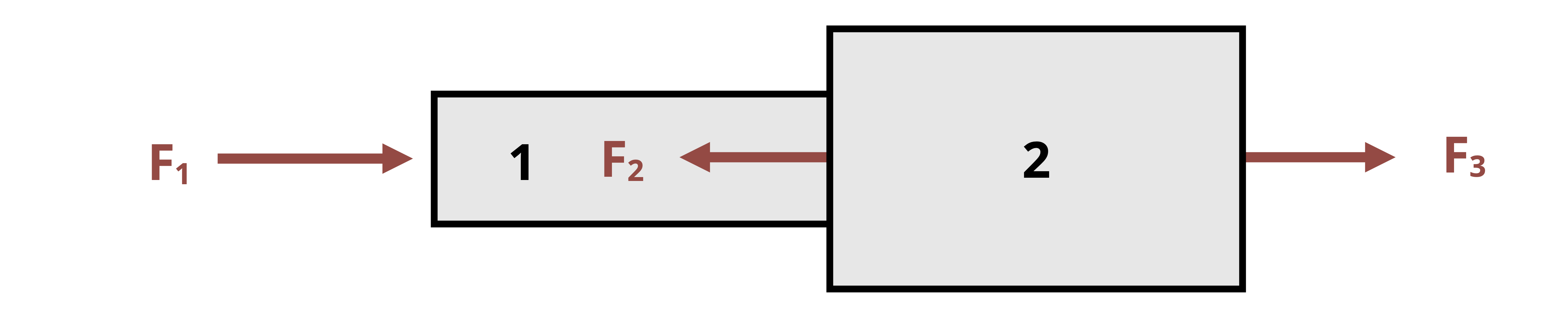
Two hollow pipes are welded together as shown. Pipe 1 has an outer diameter of 70 mm and an inner diameter of 40 mm, while pipe 2 has an outer diameter of 110 mm and an inner diameter of 60 mm. Forces are applied at the end of each pipe and at the weld, where F1 = 40 kN, F2 = 70 kN, and F3 = 30 kN.
Determine the average normal stress in each pipe.
We can calculate average normal stress using \(\sigma=\frac{N}{A}\), so we need to find the area of each pipe and the normal force in each pipe. This can be completed in any order. Starting with the areas, calculate as follows:
\[ \begin{aligned} & A_1=\pi\left(0.035^2-0.02^2\right)=0.00259{~m}^2 \\ & A_2=\pi\left(0.055^2-0.03^2\right)=0.00668{~m}^2 \end{aligned} \]
The internal loads can be found by cutting a cross-section through each pipe, drawing a free body diagram, and writing an equilibrium equation.
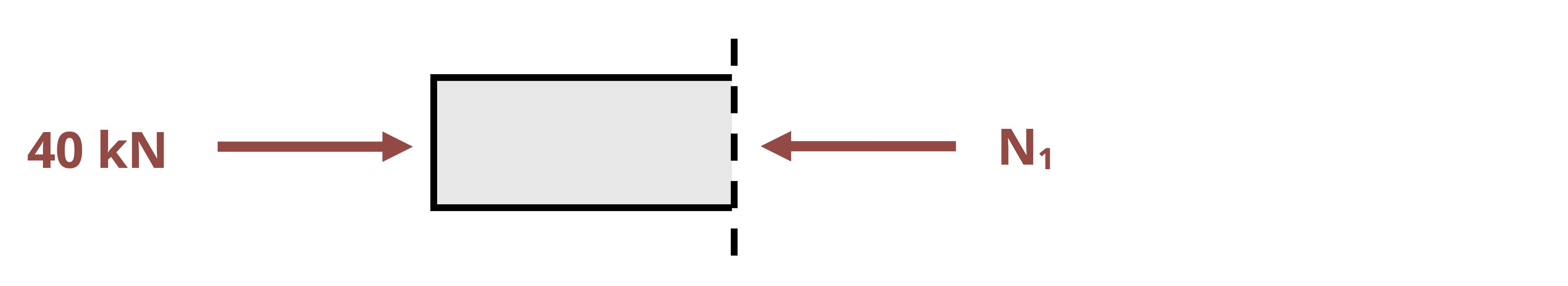
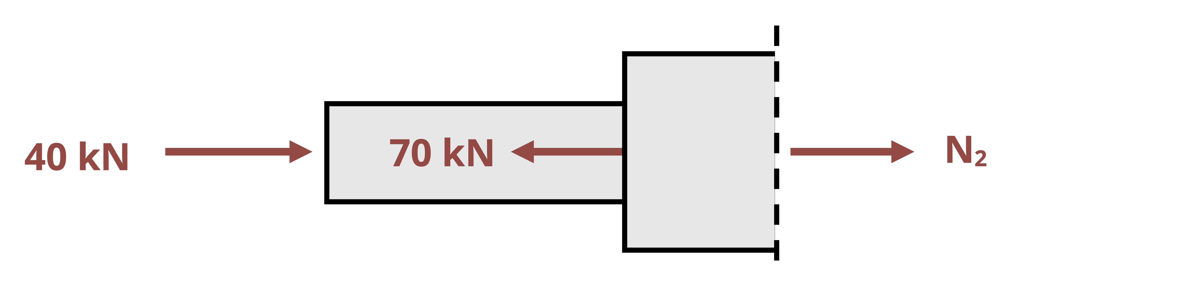
\[ \begin{aligned} &\sum F_x=40{~kN}-N_1=0 \quad \rightarrow \quad N_1=40{~kN} \\ &\sum F_x=40{~kN}-70{~kN}+N_2=0 \quad \rightarrow \quad N_2=30{~kN} \end{aligned} \]
Note that we may choose to draw the internal load in either tension or compression. The answer must be compared to the FBD. A positive answer from the equilibrium equation indicates that the direction drawn on the FBD is correct. Although both answers here are positive, the FBD shows that N1 is drawn in compression and N2 is drawn in tension. These positive answers indicate that the drawings are correct. N1 is 40 kN in compression and N2 is 30 kN in tension.
Note also that it is acceptable to draw an FBD of either side of the cross-section. This doesn’t change the result. Perhaps drawing the right-hand side of section 2 would have been an easier approach.
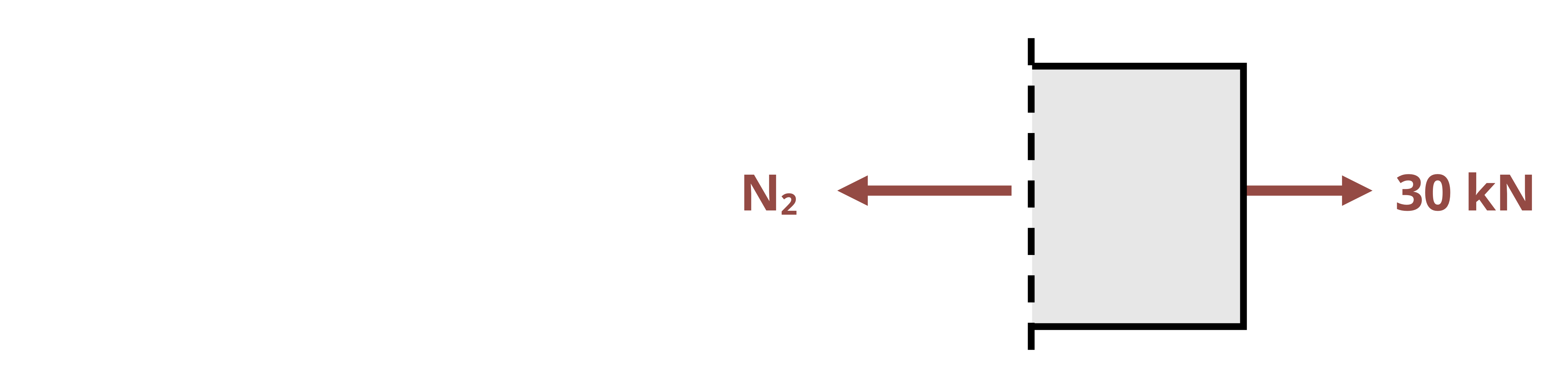
\[ \sum F_x=30{~kN}+N_2=0 \quad \rightarrow \quad N_2=30{~kN} \]
We again find that N2 is 30 kN in tension. You may always choose to draw either one side of a cross-section or the other. Make sure to include everything on the chosen side of your cut, all the way to the end of the structure (e.g., don’t stop at the weld).
Now that the areas and internal loads are known, we can calculate the internal normal stresses.
\[ \begin{gathered} \sigma_1=\frac{N_1}{A_1}=\frac{-40,000{~N}}{0.00259{~m}^2}=-15.4{~MPa} \\ \sigma_2=\frac{N_2}{A_2}=\frac{30,000{~N}}{0.00668{~m}^2}=4.49{~MPa} \end{gathered} \]
2.2 Average Shear Stress
Click to expand
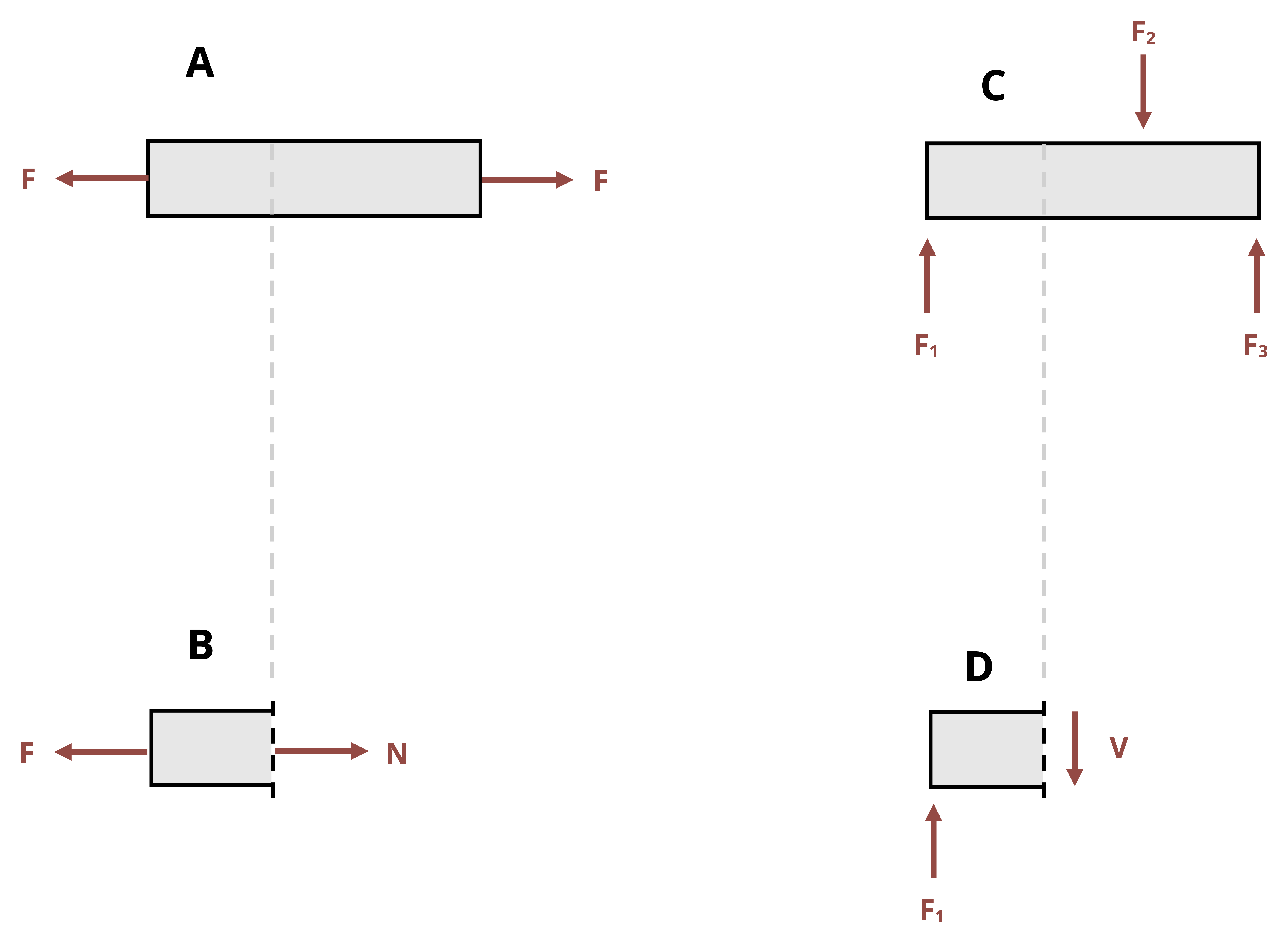
Average shear stress is defined as the internal shear force divided by the cross-sectional area of the body. While normal forces (and therefore normal stresses) occur when a body is under tension or compression, shear forces (and therefore shear stresses) occur when a force is tangentially applied parallel to the cross-section, resulting in a sliding motion (Figure 2.3).
Although the basic definition of average normal stress and average shear stress is the same—force divided by area—there are some differences. To differentiate which stress we’re talking about, we denote shear stress by the Greek letter tau (τ).
\[ \boxed{\tau=\frac{V}{A}}\text{ ,} \tag{2.2}\]
τ = Average shear stress [Pa, psi]
V = Internal shear force [N, lb]
A = Cross-sectional area [m2, in.2]
Like normal force, internal shear force can be found by cutting a cross-section through the body, drawing an FBD, and applying equilibrium equations. See Example 2.3 for a demonstration.
Example 2.3
A bridge spans a gap of L = 150 ft. The roadway may be considered simply supported and has a rectangular cross-section of base b = 10 in. and height h = 6 in. It is subjected to a uniform distributed load of w = 200 lb/ft.
Determine the magnitude of the average shear stress in the cross-section at x = 30 ft and x = 80 ft.
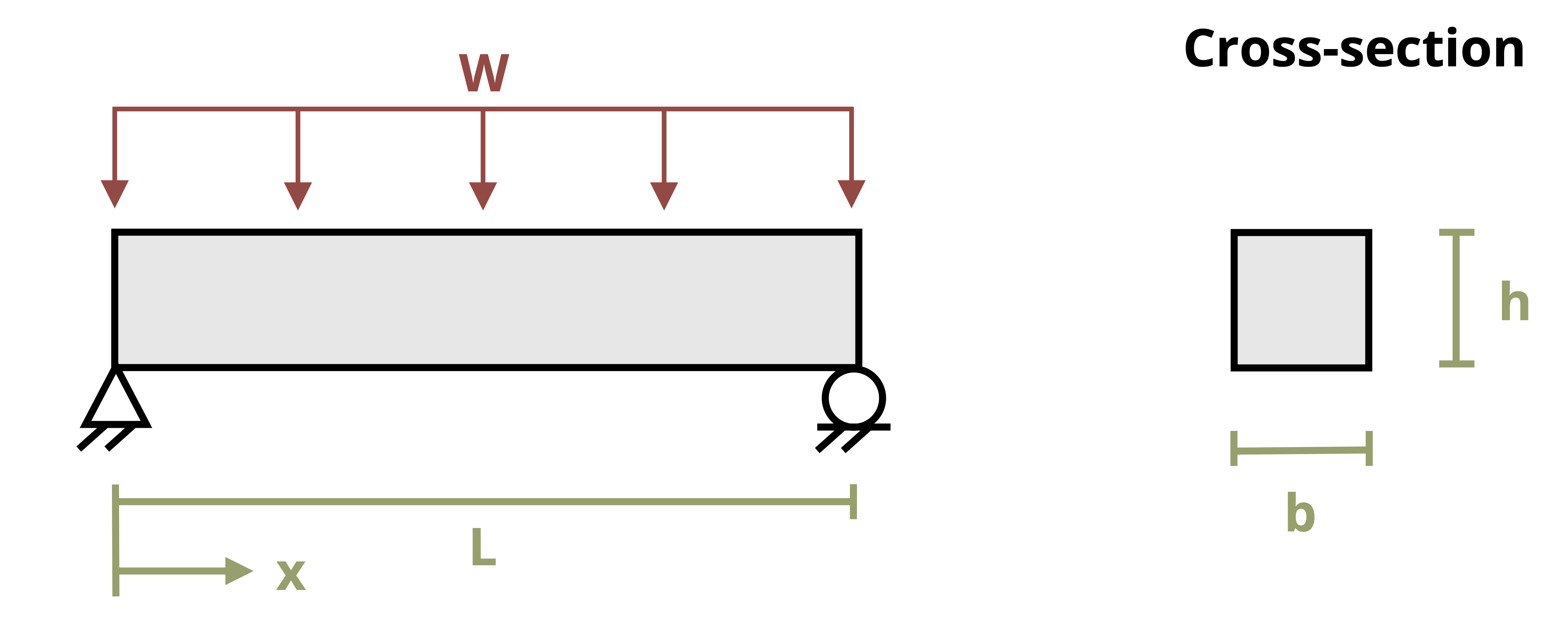
Average shear stress can be calculated from \(\tau=\frac{V}{A}\). The cross-sectional area is \(A=10{~in.}*6{~in.}=60{~in.}^2\)
The reactions at the support can be found by converting the distributed load into a statically equivalent concentrated load. This load will be equal to \(F=200{~lb/ft}*150{~ft}=30,000{~lb}\) and will be located at the center of the bridge. Since the loading is symmetric, each support will support half this load, or 15,000 lb each.
The internal shear force can be found by cutting a cross-section through the point of interest, drawing an FBD, and applying equilibrium equations. Remember to include the internal loads V and M and to again convert the distributed load into a statically equivalent concentrated load over this portion of the bridge.
At x = 30 ft:
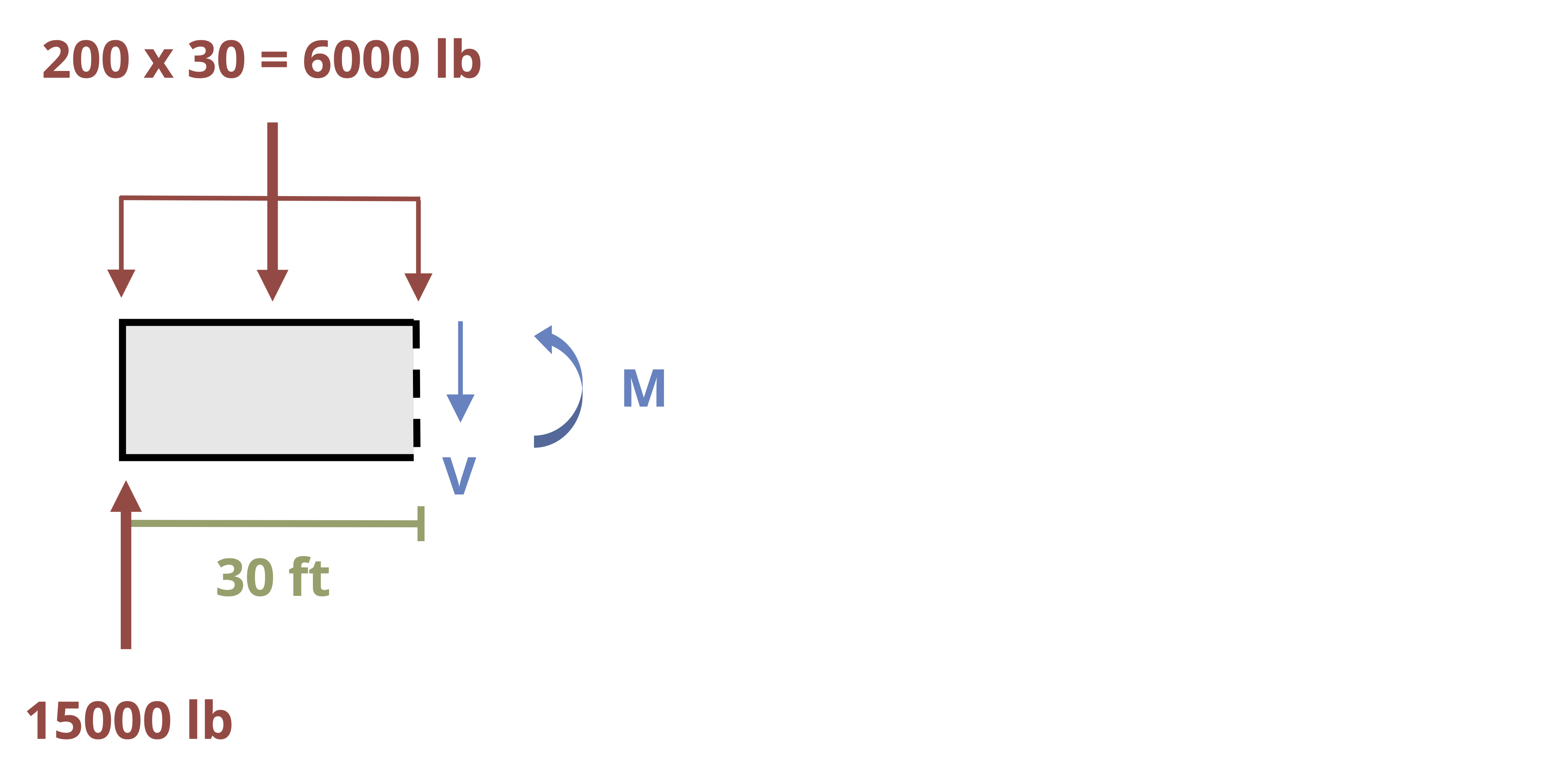
\[ \sum F_y=15,000{~lb}-6,000{~lb}-V=0 \quad \rightarrow \quad V=9,000{~lb} \]
Note that an internal bending moment is also necessary to maintain equilibrium. We could find M by summing moments about any point, but the step is not required to solve this problem.
The shear stress can now be calculated.
\[ \tau=\frac{V}{A}=\frac{9,000{~lb}}{60{~in.}^2}=150{~psi} \]
At x = 80 ft:
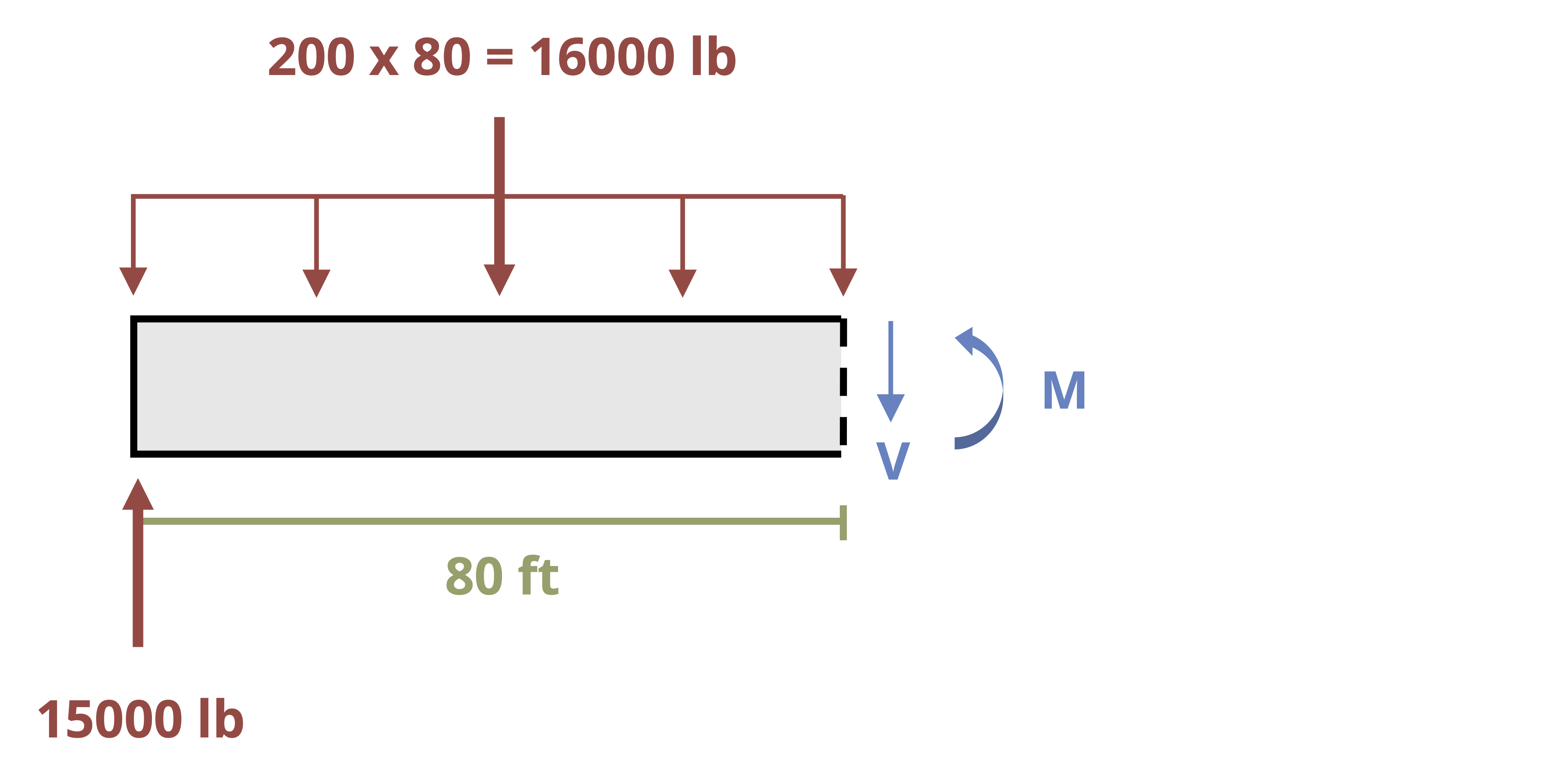
\[ \sum F_y=15,000{~lb}-16,000{~lb}-V=0 \quad \rightarrow \quad V=-1,000{~lb} \]
The negative sign here simply indicates that V is acting in the opposite direction of that drawn in the FBD. It can be discarded here because we are calculating the magnitude of the average shear stress at each point.
\[ \tau=\frac{V}{A}=\frac{1,000{~lb}}{60{~in.}^2}=16.7{~psi} \]
Shear stresses are common in both members of a structure and also in the fasteners between members. Depending on how these connections are formed, we may see multiple shear planes. It is very important to correctly identify the internal force in the body. Figure 2.4 demonstrates the difference between single and double shear configurations for a pinned joint and the effects on internal shear force. Notice that in the case of double shear, the internal shear force is half that of the applied force, F1. See Example 2.4 for an example of double shear.
Example 2.4
A pin made of a tin alloy with an allowable shear stress of 3 ksi is used to connect a footrest to the frame of a motorcycle. When in motion, the footrest supports a load of 200 lb, which is transferred to the pin.
Determine the required diameter of the pin such that the stress will not exceed 3 ksi.
.png)
Average shear stress can be calculated from \(\tau=\frac{V}{A}\). Rearrange this equation to \(A=\frac{V}{\tau}\). Start with an FBD of the pin to determine the internal shear force.
From the diagram it should be apparent that the pin is in double shear and the maximum internal shear force in the pin is 100 lb. Thus the required cross-sectional area \(A=\frac{100{~lb}}{3,000{~psi}}=0.0333{~in.}^2\).
Since \(A=\frac{\pi}{4} d^2\), the required diameter is \(d=\sqrt{\frac{0.0333{~in.}^2 * 4}{\pi}}=0.206{~in}\).
2.3 Bearing Stress
Click to expand
Bearing stress is similar to normal stress, except that it occurs at the contact area between two bodies instead of within a single body. Bearing stress is calculated with the average normal stress equation, where the cross-sectional area is the contact area between the two bodies (Figure 2.5).
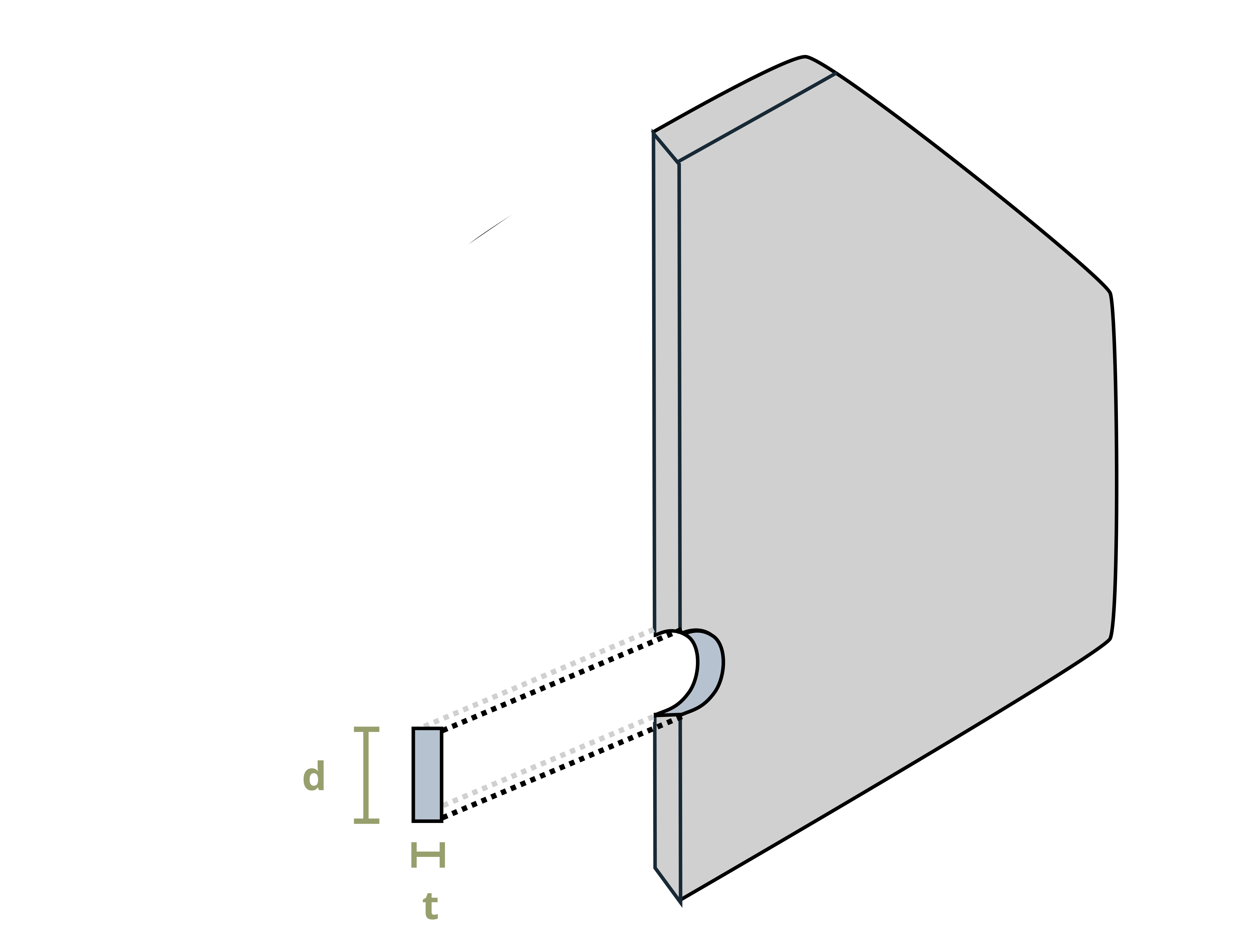
One common situation is contact between two curved edges, such as the bolt in Figure 2.6. In this situation it is common to use the projected contact area between the curved surfaces, which forms a rectangle of base d and height t.
\[ A=d*t \]
This greatly simplifies the calculation but again represents an average value for the contact or bearing stress. See Example 2.5 for a problem involving the bearing stress between a bolt and a plate.
Example 2.5
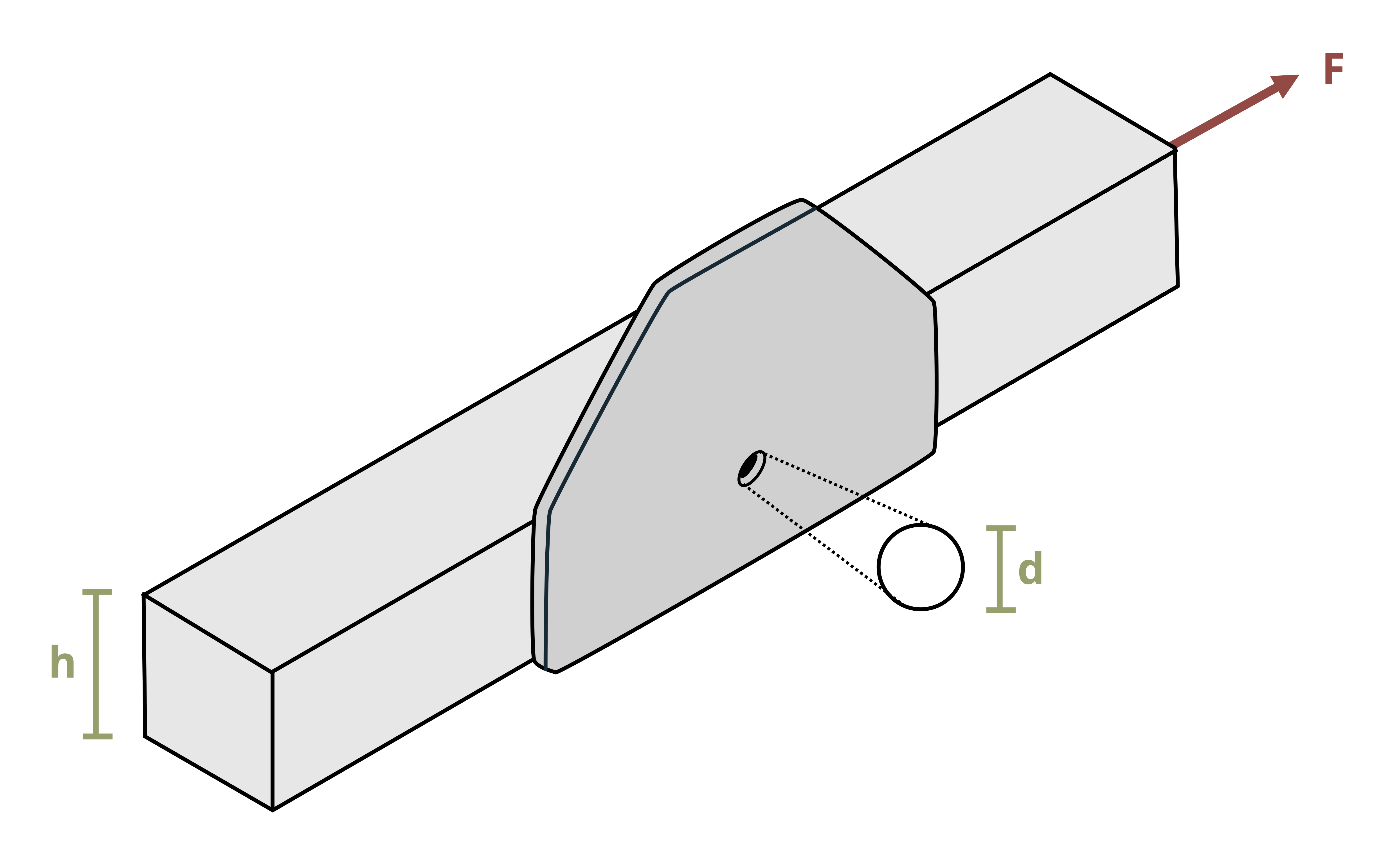
A bolt of diameter d = 80 mm is used to attach a steel bar to a gusset plate. The steel bar dimensions are height h = 200 mm and thickness t = 30 mm. It is subjected to a tensile force F = 50 kN.
Determine the bearing stress created in the steel bar at the pin.
Bearing stress can be calculated from \(\sigma=\frac{N}{A}\), where N is the normal force between the objects and A is the projected contact area.
The force between the pin and the bar will be \(F=50~kN = 50,000~N\).
The projected contact area between the pin and the plate can be found from the diameter of the pin \((80~mm=0.08~m)\) multiplied by the thickness of the plate \((30~mm=0.03~m)\).
\[ A=d*t=0.08*0.03=0.0024~m^2 \]
Now we can calculate the bearing stress.
\[ \sigma=\frac{50,000~N}{0.0024~m^2}=20.8*10^6~Pa=20.8~MPa \]
2.4 Stress on an Inclined Plane
Click to expand
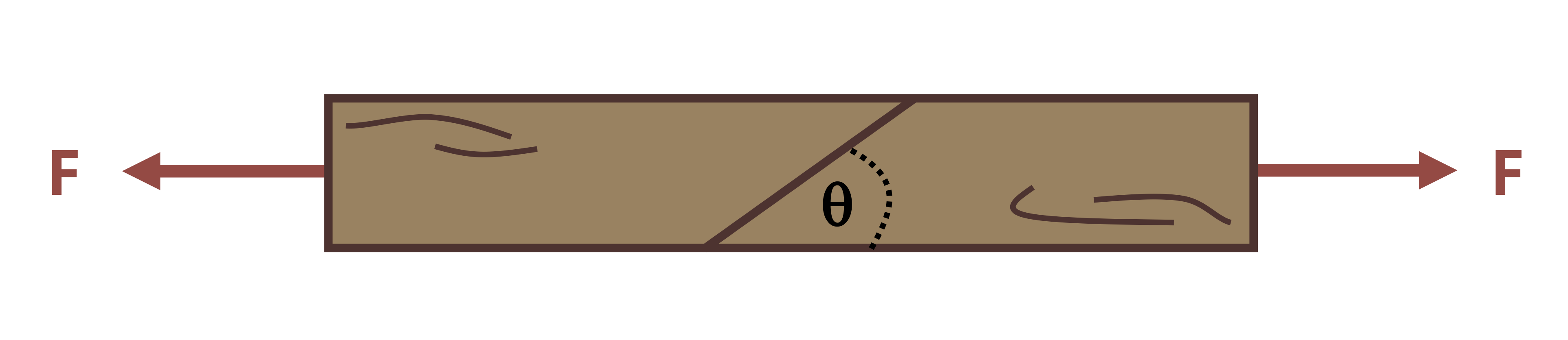
We have so far been cutting cross-sections perpendicular to the external force or parallel to it. However, no rule says we have to do this. It is perfectly acceptable to cut cross-sections at an angle, and in many situations it may make sense to do so (Figure 2.7).
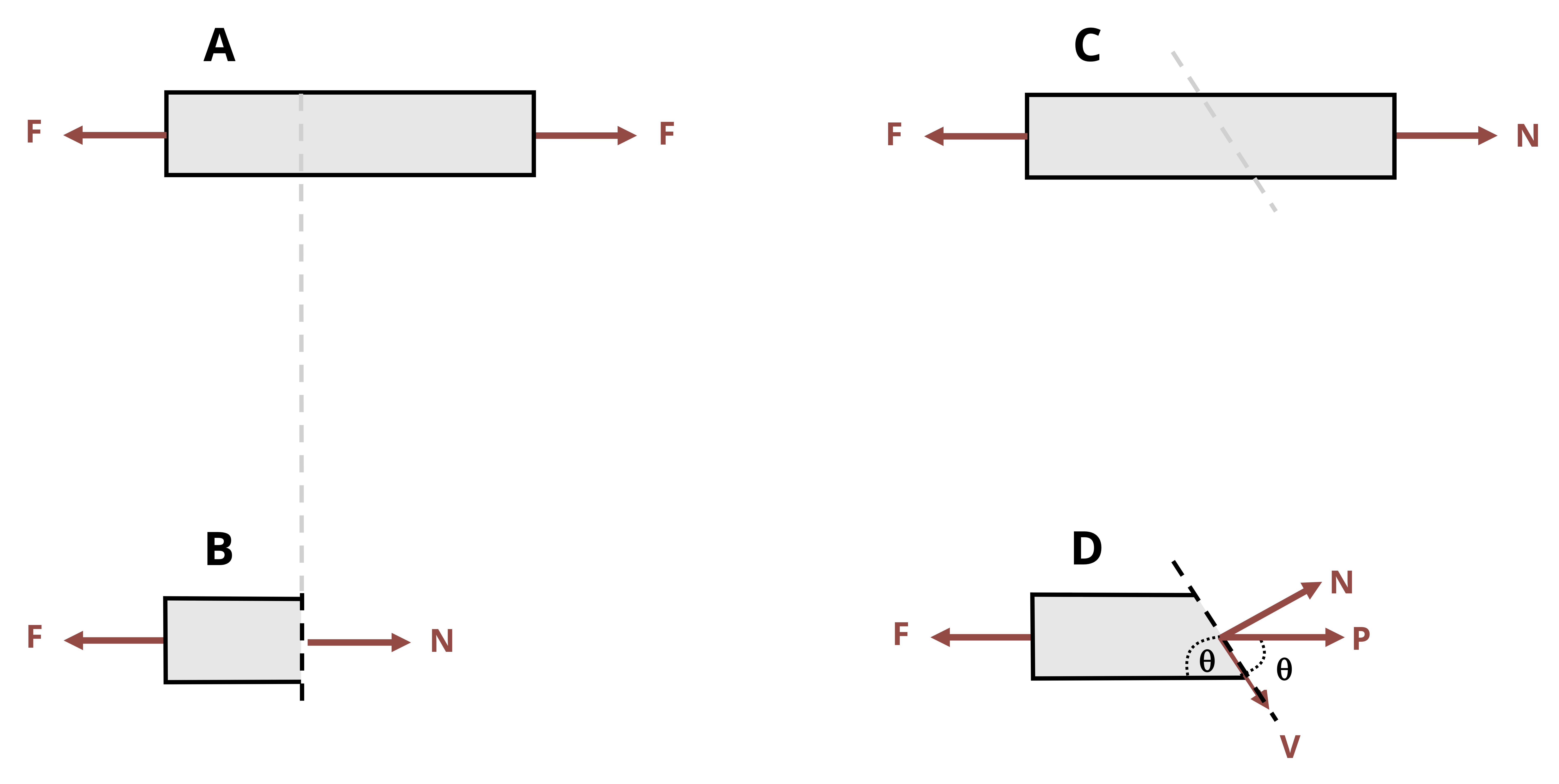
In this scenario, to maintain equilibrium the internal load must still be equal and opposite to the external load, but because the cross-section is cut at an angle, this internal load is neither parallel nor perpendicular to the cross-section. Therefore, it is not entirely a normal force or a shear force. However, the internal force may be broken into components that are perpendicular and parallel to the cross-section.
\[ \begin{aligned} & N=P \sin (\theta) \\ & V=P \cos (\theta) \end{aligned} \]
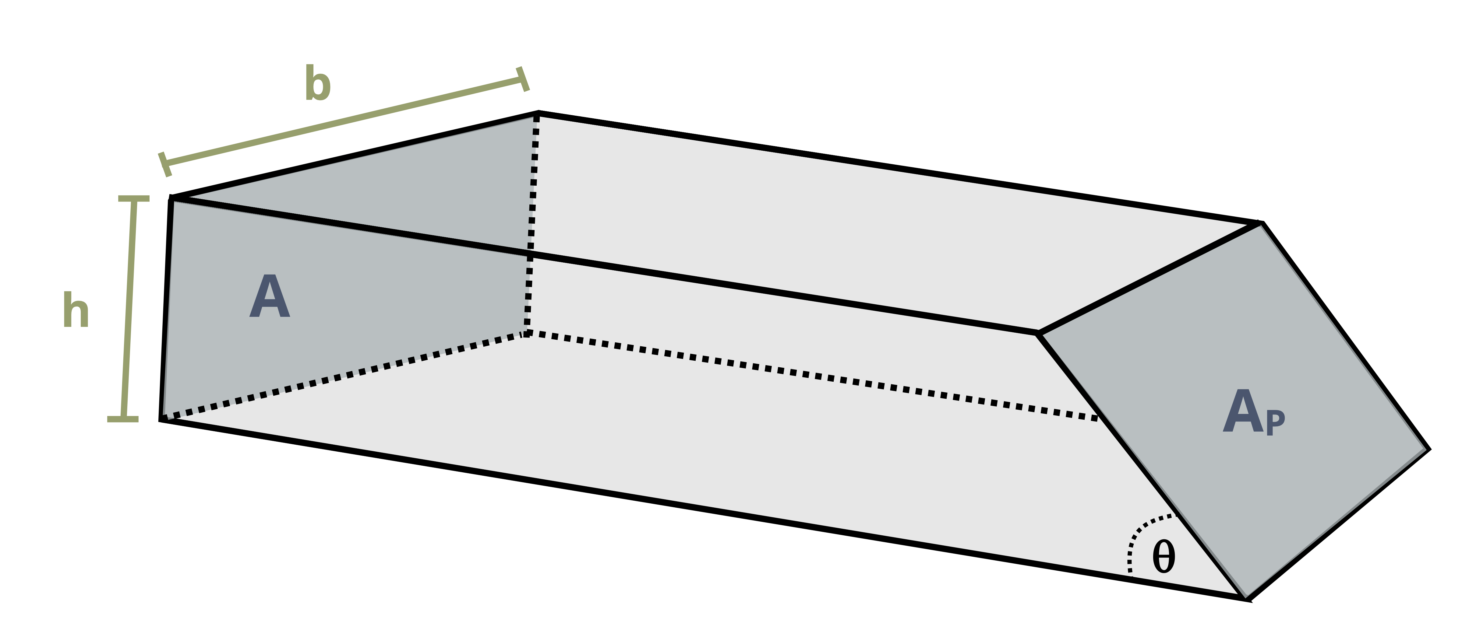
The area used to calculate the average normal and shear stresses must be the area of the inclined plane (Figure 2.8). Setting up a right-angled triangle enables us to find the area of the plane, Ap.
\[ A_p=\frac{A}{\sin (\theta)} \]
We can then calculate average normal stress.
\[\boxed{\sigma=\frac{N}{A_p}=\frac{P \sin (\theta)}{\frac{A}{\sin (\theta)}}=\frac{P \sin ^2(\theta)}{A}} \tag{2.3}\]
We can calculate average shear stress from
\[\boxed{\tau=\frac{V}{A_p}=\frac{P \cos (\theta)}{\frac{A}{\sin (\theta)}}=\frac{P \sin (\theta) \cos (\theta)}{A}}\text{ ,} \tag{2.4}\]
𝜎 = Average normal stress on the inclined plane [Pa, psi]
τ = Average shear stress on the inclined plane [Pa, psi]
N = Internal normal force perpendicular to the inclined plane [N, lb]
V = Internal shear force parallel to the inclined plane [N, lb]
Ap = Area of the inclined plane [m2, in.2]
A = Cross-sectional area [m2, in.2]
P = Internal load perpendicular to cross-sectional area A [N, lb]
𝜃 = Angle between the inclined plane and the axis perpendicular to cross-sectional area A [°]
These equations assume the angle (θ) is measured from the axis perpendicular to area A. For a horizontal beam, area A is in the vertical plane, so angle θ is measured from the horizontal axis.
Even if the external load remains constant, we can obtain different values for the internal normal and shear forces (and therefore different values for the stresses) by changing the angle at which we cut the cross-section. Chapter 12 explores the implications. For now, a demonstration of calculating the stresses on an inclined plane is given in Example 2.6.
Example 2.6
A beam is formed of two structural wooden members glued together along an inclined plane at angle θ = 40° and subjected to a tensile force of F = 30 kN. The height of the beam is 50 mm and its thickness is 20 mm.
Determine the normal and shear stresses created along the inclined plane.
Begin by cutting a cross-section along the inclined plane and drawing an FBD. Remember to include the internal normal and shear forces perpendicular and parallel to the cross-section.
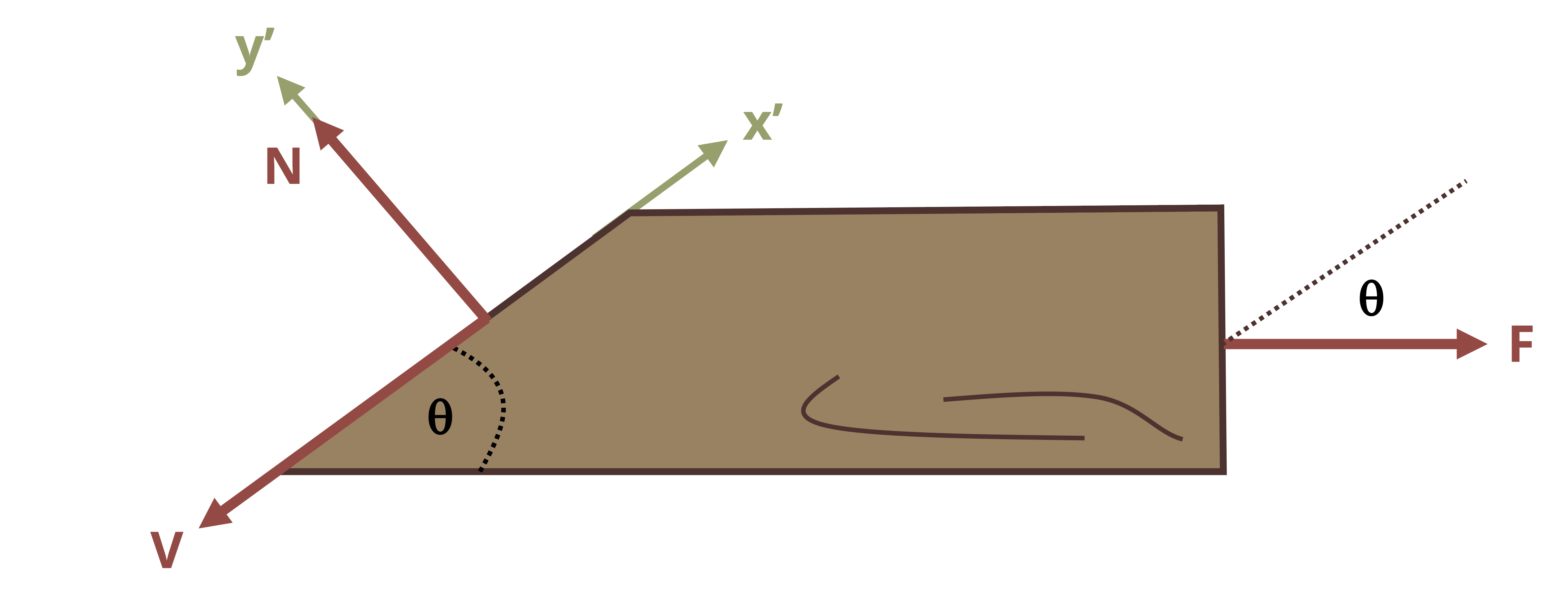
Use equilibrium equations to determine the internal forces. It will be easiest to define axes parallel and perpendicular to the inclined plane.
\[ \begin{aligned} \sum F_{x^{\prime}}= F \cos (\theta)-V=0 \\ \sum F_{y^{\prime}}= N-F \sin (\theta)=0 \end{aligned} \]
With F = 30 kN and θ = 40°, these can be solved for.
\[ \begin{aligned} \sum F_{x^{\prime}}= 30{~kN} \cos (40^{\circ})-V=0 \\ V = 23.0{~kN}\\ \sum F_{y^{\prime}}= N-30{~kN} \sin (40^{\circ})=0\\ N=19.3{~kN} \end{aligned} \]
N = 19.3 kN and V = 23.0 kN.
Next, determine the cross-sectional area of the inclined plane.
\[ A_p=\frac{A}{\sin (\theta)} \]With \(A = 0.05{~m}*0.02{~m} = 0.001{~m}^2\) and \(θ = 40°\), \(Ap = 0.00156{~m}^2\).
Finally, determine the average normal stress and the average shear stress.
\[ \begin{aligned} \sigma & =\frac{N}{A_p}=\frac{19,300{~N}}{0.00156{~m}^2}=12.4 \times 10^6 \frac{{N}}{m^2}=12.4{~MPa} \\ \tau & =\frac{V}{A_p}=\frac{23,000{~N}}{0.00156{~m}^2}=14.8 \times 10^6 \frac{\mathrm{N}}{m^2}=14.8{~MPa} \end{aligned} \]
Summary
Click to expand
References
Click to expand
Figures
All figures in this chapter were created by Kindred Grey in 2025 and released under a CC BY license, except for
Figure 2.1: Forces pulling on a cross-section cause tension, while forces pushing on a cross-section cause compression. Left image: Orangeaurochs. 2012. CC BY 2.0. https://flic.kr/p/dqmXdM. Right image: Unknown author. 2017. Public domain. https://pxhere.com/en/photo/993074. Diagrams: Kindred Grey. 2024. CC BY.
Example 2.1: Jbarta. 2010. CC BY-SA 3.0. https://en.wikipedia.org/wiki/File:Permanent-column-form.jpg.
Example 2.4: Image: James Lord. CC BY NC-SA.
Figure 2.5: Circular column sitting upon a rectangular foundation. Jiří Sedláček - Frettie. 2010. CC BY-SA 3.0. https://commons.wikimedia.org/wiki/File:Footing_of_column_in_collections_of_Muzeum_Vyso%C4%8Diny_in_T%C5%99eb%C3%AD%C4%8D,_T%C5%99eb%C3%AD%C4%8D_District.jpg.